The Adventures of OS
使用Rust的RISC-V操作系统 在Patreon上支持我! 操作系统博客 RSS订阅 Github EECS网站 这是用Rust编写RISC-V操作系统系列教程中的第10章。 目录 → 第8章 → (第9章) → 第10章
块设备驱动
2020年4月6日:仅限PATREON
2020年4月13日:公开
视频和参考资料
我在大学里教过操作系统,所以我将在这里链接我在那门课程中关于virt I/O协议的笔记。这个协议多年来一直在变化,但QEMU实现的是传统的MMIO接口。
https://www.youtube.com/watch?v=FyPnYxeH5YU
https://docs.oasis-open.org/virtio/virtio/v1.1/virtio-v1.1.html
上面的说明是对进程这一概念的总体概述。 我们在这里构建的操作系统可能会做一些不同的事情。这主要是因为它是用Rust编写的--hahahahaha。
概述
VirtIO协议是一种与虚拟化设备通信的方式,例如块状设备(硬盘)或输入设备(鼠标/键盘)。 在这篇文章中,我将向你展示如何使用VirtIO协议编写一个块驱动。
首先,我们必须了解的是,VirtIO只是一个通用的I/O通信协议。然后,我们要看一下块设备部分,看看专门针对块设备的通信协议。
非持久性指针
使用内存映射的I/O通常需要使用非持久性指针。这是C/C++中的一个特定关键字,它告诉编译器,指针所给的内存地址的值可能发生非显性的变化。这意味着编译器不能对其进行以内存值不变为前提的优化。
在C/C++中,这是在声明指针时使用的一个关键字。然而,Rust没有这样一个关键字。相反,Rust使用一个原始指针的成员,称为read_volatile或write_volatile: https://doc.rust-lang.org/nightly/std/primitive.pointer.html#method.read_volatile.
这可能会导致一些问题,虽然在"读"的时候不是太糟糕,但在"写"的时候却是一场噩梦。有两种不同的方法来解决对MMIO的读/写。(1)创建一个大的结构,其字段方便地与偏移量对齐(2)每次读和写都计算偏移量。我个人更喜欢#1的便利性和可读性,然而,Rust让#1变得更加困难。在调试了很久之后,我决定采用#2。虽然我还没有放弃,但在这一点上,更多的是固执己见,没有什么收获。
为了帮助我做到这一点,我创建了一个包含所有偏移量的枚举,这些偏移量包含在了VirtIO规范中。
#![allow(unused)]
fn main() {
#[repr(usize)]
pub enum MmioOffsets {
  MagicValue = 0x000,
  Version = 0x004,
  DeviceId = 0x008,
  VendorId = 0x00c,
  HostFeatures = 0x010,
  HostFeaturesSel = 0x014,
  GuestFeatures = 0x020,
  GuestFeaturesSel = 0x024,
  GuestPageSize = 0x028,
  QueueSel = 0x030,
  QueueNumMax = 0x034,
  QueueNum = 0x038,
  QueueAlign = 0x03c,
  QueuePfn = 0x040,
  QueueNotify = 0x050,
  InterruptStatus = 0x060,
  InterruptAck = 0x064,
  Status = 0x070,
  Config = 0x100,
}
}
开头的repr意味着将这些数据表示为数据类型usize,对于一个64位的系统来说,它是64位。我们不需要这么多的存储空间,但是当我们向一个指针添加数据时,Rust想要一个usize,而不是一个u16。
你会注意到,如果你阅读VirtIO规范,这些是传统的偏移量。这是因为QEMU在使用VirtIO时,暂时使用传统的MMIO接口。
关于指针偏移的说明
就像C/C++一样,当我们在Rust中向一个指针添加一个值时,它是作为一个缩放的偏移量添加的。这意味着,如果我给一个u64的指针加1,它实际上是加8。对于任何指针来说,公式是base + offset * size。
这将导致问题,因为我在这个枚举中有绝对偏移量的数字。为了将其与Rust的原始指针联系起来,我在枚举中加入了一些成员。
#![allow(unused)]
fn main() {
impl MmioOffsets {
  pub fn val(self) -> usize {
    self as usize
  }

  pub fn scaled(self, scale: usize) -> usize {
    self.val() / scale
  }

  pub fn scale32(self) -> usize {
    self.scaled(4)
  }

}
}
第一个成员中,fn val将获取枚举类型并将其转换为等价的usize。这是因为Rust不能自动完成这种转化。
然后,我们有scale32()。我把它作为一个辅助工具,因为我用一个32位的指针(大多数寄存器都是32位的)来作为相对MMIO读/写基址的偏移。
你可以看到,我并不特别喜欢这种方法。结构方法使它更容易在不同的数据大小之间切换,但现在,这是我选择的方法。
扫描总线
我不会在这里介绍VirtIO协议,对应地,我已经把我的讲义链接到上面的操作系统课。相反,我选择让操作系统发挥作用。我将截取一些说明,如果你需要更深入地了解该协议,请看课程笔记。
对于QEMU模拟器来说,它把virtio设备按地址映射为0x1000_1000到0x1000_8000。如果我们只有一个设备,它应该连接在0x1000_8000处,但为了良好的操作系统实践,我们要探测所有总线,看看连接了什么。
#![allow(unused)]
fn main() {
pub fn probe() {
  // Rust's for loop uses an Iterator object, which now has a step_by
  // modifier to change how much it steps. Also recall that ..= means up
  // to AND including MMIO_VIRTIO_END.
  for addr in (MMIO_VIRTIO_START..=MMIO_VIRTIO_END).step_by(MMIO_VIRTIO_STRIDE) {
    print!("Virtio probing 0x{:08x}...", addr);
    let magicvalue;
    let deviceid;
    let ptr = addr as *mut u32;
    unsafe {
      magicvalue = ptr.read_volatile();
      deviceid = ptr.add(2).read_volatile();
    }
    // 0x74_72_69_76 is "virt" in little endian, so in reality
    // it is triv. All VirtIO devices have this attached to the
    // MagicValue register (offset 0x000)
    if MMIO_VIRTIO_MAGIC != magicvalue {
      println!("not virtio.");
    }
    // If we are a virtio device, we now need to see if anything
    // is actually attached to it. The DeviceID register will
    // contain what type of device this is. If this value is 0,
    // then it is not connected.
    else if 0 == deviceid {
      println!("not connected.");
    }
    // If we get here, we have a connected virtio device. Now we have
    // to figure out what kind it is so we can do device-specific setup.
    else {
      match deviceid {
        // DeviceID 2 is a block device
        2 => {
          print!("block device...");
          if false == setup_block_device(ptr) {
            println!("setup failed.");
          }
          else {
            let idx = (addr - MMIO_VIRTIO_START) >> 12;
            unsafe {
              VIRTIO_DEVICES[idx] =
                Some(VirtioDevice::new_with(DeviceTypes::Block));
            }
            println!("setup succeeded!");
          }
        },
        // DeviceID 4 is a random number generator device
        4 => {
          print!("entropy device...");
          if false == setup_entropy_device(ptr) {
            println!("setup failed.");
          }
          else {
            println!("setup succeeded!");
          }
        },
        _ => println!("unknown device type."),
      }
    }
  }
}
}
在探测过程中,我们首先要看这是否是一个virtio的基础地址。在偏移量0处,我们应该读到4个字节,这将是 "triv",也就是以little-endian形式存储的 "virt"。这被称为magic字节,用于识别目的。如果我们发现这个magic不匹配,那么我们可以确信这不是一个virtio内存地址。
在我们发现这是一个virtio总线之后,我们要看看实际上连接的是什么类型的设备。回想一下,virtio是一个通用的总线,所以我们可以连接GPU、网络设备、块状设备,等等。我们可以通过读取DeviceID寄存器来判断连接的设备类型。现在,我们只关心设备号2,它是为块设备保留的。
如果我们找到 "virt "和设备ID 2,我们就可以把这个设备配置为一个块设备。这时我们就可以看到规范中关于设备的具体部分。
配置设备
在我们能够使用设备之前,我们必须配置它。我们与设备(它们)协商驱动程序(我们),按照程序来完成这一工作。
配置设备的程序在规范中规定如下。
- 通过向状态寄存器写0来重置设备。
- 在状态寄存器中设置ACKNOWLEDGE状态位。
- 将DRIVER的状态位设置到状态寄存器中。
- 从host_features寄存器中读取设备特性。
- 协商功能集,并将接受的内容写入guest_features寄存器。
- 将FEATURES_OK状态位设置到状态寄存器中。
- 重新读取状态寄存器,确认设备接受了你的功能。
- 执行设备特定的设置。
- 在状态寄存器中设置DRIVER_OK状态位,设备将被激活。
看起来有很多步骤,但其实并不难。我们正在做的是确保驱动程序和设备能够相互理解。其中一个 "功能 "可能是只读位,这意味着我们不能写到设备上。如果我们想写到设备上,我们可能要协商关闭这个功能。
#![allow(unused)]
fn main() {
pub fn setup_block_device(ptr: *mut u32) -> bool {
  unsafe {
    // We can get the index of the device based on its address.
    // 0x1000_1000 is index 0
    // 0x1000_2000 is index 1
    // ...
    // 0x1000_8000 is index 7
    // To get the number that changes over, we shift right 12 places (3 hex digits)
    let idx = (ptr as usize - virtio::MMIO_VIRTIO_START) >> 12;
    // [Driver] Device Initialization
    // 1. Reset the device (write 0 into status)
    ptr.add(MmioOffsets::Status.scale32()).write_volatile(0);
    let mut status_bits = StatusField::Acknowledge.val32();
    // 2. Set ACKNOWLEDGE status bit
    ptr.add(MmioOffsets::Status.scale32()).write_volatile(status_bits);
    // 3. Set the DRIVER status bit
    status_bits |= StatusField::DriverOk.val32();
    ptr.add(MmioOffsets::Status.scale32()).write_volatile(status_bits);
    // 4. Read device feature bits, write subset of feature
    // bits understood by OS and driver    to the device.
    let host_features = ptr.add(MmioOffsets::HostFeatures.scale32()).read_volatile();
    let guest_features = host_features & !(1 << VIRTIO_BLK_F_RO);
    let ro = host_features & (1 << VIRTIO_BLK_F_RO) != 0;
    ptr.add(MmioOffsets::GuestFeatures.scale32()).write_volatile(guest_features);
    // 5. Set the FEATURES_OK status bit
    status_bits |= StatusField::FeaturesOk.val32();
    ptr.add(MmioOffsets::Status.scale32()).write_volatile(status_bits);
    // 6. Re-read status to ensure FEATURES_OK is still set.
    // Otherwise, it doesn't support our features.
    let status_ok = ptr.add(MmioOffsets::Status.scale32()).read_volatile();
    // If the status field no longer has features_ok set,
    // that means that the device couldn't accept
    // the features that we request. Therefore, this is
    // considered a "failed" state.
    if false == StatusField::features_ok(status_ok) {
      print!("features fail...");
      ptr.add(MmioOffsets::Status.scale32()).write_volatile(StatusField::Failed.val32());
      return false;
    }
    // 7. Perform device-specific setup.
    // Set the queue num. We have to make sure that the
    // queue size is valid because the device can only take
    // a certain size.
    let qnmax = ptr.add(MmioOffsets::QueueNumMax.scale32()).read_volatile();
    ptr.add(MmioOffsets::QueueNum.scale32()).write_volatile(VIRTIO_RING_SIZE as u32);
    if VIRTIO_RING_SIZE as u32 > qnmax {
      print!("queue size fail...");
      return false;
    }
    // First, if the block device array is empty, create it!
    // We add 4095 to round this up and then do an integer
    // divide to truncate the decimal. We don't add 4096,
    // because if it is exactly 4096 bytes, we would get two
    // pages, not one.
    let num_pages = (size_of::<Queue>() + PAGE_SIZE - 1) / PAGE_SIZE;
    // println!("np = {}", num_pages);
    // We allocate a page for each device. This will the the
    // descriptor where we can communicate with the block
    // device. We will still use an MMIO register (in
    // particular, QueueNotify) to actually tell the device
    // we put something in memory. We also have to be
    // careful with memory ordering. We don't want to
    // issue a notify before all memory writes have
    // finished. We will look at that later, but we need
    // what is called a memory "fence" or barrier.
    ptr.add(MmioOffsets::QueueSel.scale32()).write_volatile(0);
    // Alignment is very important here. This is the memory address
    // alignment between the available and used rings. If this is wrong,
    // then we and the device will refer to different memory addresses
    // and hence get the wrong data in the used ring.
    // ptr.add(MmioOffsets::QueueAlign.scale32()).write_volatile(2);
    let queue_ptr = zalloc(num_pages) as *mut Queue;
    let queue_pfn = queue_ptr as u32;
    ptr.add(MmioOffsets::GuestPageSize.scale32()).write_volatile(PAGE_SIZE as u32);
    // QueuePFN is a physical page number, however it
    // appears for QEMU we have to write the entire memory
    // address. This is a physical memory address where we
    // (the OS) and the block device have in common for
    // making and receiving requests.
    ptr.add(MmioOffsets::QueuePfn.scale32()).write_volatile(queue_pfn / PAGE_SIZE as u32);
    // We need to store all of this data as a "BlockDevice"
    // structure We will be referring to this structure when
    // making block requests AND when handling responses.
    let bd = BlockDevice { queue:        queue_ptr,
                            dev:          ptr,
                            idx:          0,
                            ack_used_idx: 0,
                            read_only:    ro, };
    BLOCK_DEVICES[idx] = Some(bd);

    // 8. Set the DRIVER_OK status bit. Device is now "live"
    status_bits |= StatusField::DriverOk.val32();
    ptr.add(MmioOffsets::Status.scale32()).write_volatile(status_bits);

    true
  }
}
}
要求
现在设备已经上线,我们可以通过使用virtio环开始提出请求。virtio描述符/环系统是通用的;但是,我们在进行块请求时有一个协议。我们将使用三个描述符来做一个块请求。(1)块请求头(2)块请求缓冲区(3)块请求状态。
头部告诉块设备我们是要读还是要写,以及在哪里。不幸的是,where部分的单位是扇区,而不是字节。然而,实际上字节数是扇区数的512倍。也就是说,每个扇区有512个字节。所以,这是很简单的计算。
在头部信息之后,我们存储缓冲区。对于读取操作,设备将数据写入这块内存,而对于写入,设备将从这块内存中读取数据。值得注意的是,这些必须是物理地址,因为块设备绕过了MMU。
最后,我们有一个状态字段。设备将把请求的结果写到这个8位字段。目前,我们只能得到三种响应。0-成功,1-失败,2-不支持的操作。这并没有给我们提供很多信息,但如果我们得到一个0,我们可以合理地认为我们的请求得到了正确的处理。
发出请求
为了发出一个请求,我们需要分配堆内存。我们创建的内存必须保持常驻/有效直到设备做出响应之后。因此,我们不能使用堆栈。我们将从virtio队列中抓取三个开放描述符,用头、缓冲区和状态填充它,然后我们将virtqueue的编号(0)写入queue_notify寄存器,告诉设备开始处理这个请求。
#![allow(unused)]
fn main() {
pub fn block_op(dev: usize, buffer: *mut u8, size: u32, offset: u64, write: bool) {
  unsafe {
    if let Some(bdev) = BLOCK_DEVICES[dev - 1].as_mut() {
      // Check to see if we are trying to write to a read only device.
      if true == bdev.read_only && true == write {
        println!("Trying to write to read/only!");
        return;
      }
      let sector = offset / 512;
      // TODO: Before we get here, we are NOT allowed to schedule a read or
      // write OUTSIDE of the disk's size. So, we can read capacity from
      // the configuration space to ensure we stay within bounds.
      let blk_request_size = size_of::<Request>();
      let blk_request = kmalloc(blk_request_size) as *mut Request;
      let desc = Descriptor { addr:  &(*blk_request).header as *const Header as u64,
                              len:   size_of::<Header>() as u32,
                              flags: virtio::VIRTIO_DESC_F_NEXT,
                              next:  0, };
      let head_idx = fill_next_descriptor(bdev, desc);
      (*blk_request).header.sector = sector;
      // A write is an "out" direction, whereas a read is an "in" direction.
      (*blk_request).header.blktype = if true == write {
        VIRTIO_BLK_T_OUT
      }
      else {
        VIRTIO_BLK_T_IN
      };
      // We put 111 in the status. Whenever the device finishes, it will write into
      // status. If we read status and it is 111, we know that it wasn't written to by
      // the device.
      (*blk_request).data.data = buffer;
      (*blk_request).header.reserved = 0;
      (*blk_request).status.status = 111;
      let desc = Descriptor { addr:  buffer as u64,
                              len:   size,
                              flags: virtio::VIRTIO_DESC_F_NEXT
                                      | if false == write {
                                        virtio::VIRTIO_DESC_F_WRITE
                                      }
                                      else {
                                        0
                                      },
                              next:  0, };
      let _data_idx = fill_next_descriptor(bdev, desc);
      let desc = Descriptor { addr:  &(*blk_request).status as *const Status as u64,
                              len:   size_of::<Status>() as u32,
                              flags: virtio::VIRTIO_DESC_F_WRITE,
                              next:  0, };
      let _status_idx = fill_next_descriptor(bdev, desc);
      (*bdev.queue).avail.ring[(*bdev.queue).avail.idx as usize % virtio::VIRTIO_RING_SIZE] = head_idx;
      (*bdev.queue).avail.idx = (*bdev.queue).avail.idx.wrapping_add(1);
      // The only queue a block device has is 0, which is the request
      // queue.
      bdev.dev.add(MmioOffsets::QueueNotify.scale32()).write_volatile(0);
    }
  }
}
}
上面的代码显示我们分配了三个描述符(使用kzalloc,这样它就在堆上),填充这些描述符,然后把这些描述符的头部放到available ring中。当我们把0写到queue_notify时,设备立即启动。
响应
可用的环被我们用来发出请求。被使用的*环被设备用来向我们发送响应。当我们在queue_notify中写入0时,它就开始工作。当它完成后,它将通过PLIC(还记得那个东西吗)发送一个中断。幸运的是,0x1000_1000是PLIC中断1...0x1000_8000是PLIC中断8。所以,这是一个简单的转换。
响应是以被使用的环形元素的形式出现的。当我们从这个元素读取时,我们将得到它所响应的描述符的标识符(索引)。这是因为块设备可以自由地以它所希望的任何顺序执行请求。所以!!! 我们不能假设我们会按照请求的顺序得到响应。
我们将接受一个外部中断,询问PLIC是什么原因造成的,PLIC会给我们第一个块设备的8。当我们看到这一点时,我们可以将数据转发给该块设备的处理程序,然后它将确认响应。
#![allow(unused)]
fn main() {
pub fn pending(bd: &mut BlockDevice) {
  // Here we need to check the used ring and then free the resources
  // given by the descriptor id.
  unsafe {
    let ref queue = *bd.queue;
    while bd.ack_used_idx != queue.used.idx {
      let ref elem = queue.used.ring[bd.ack_used_idx as usize % VIRTIO_RING_SIZE];
      bd.ack_used_idx = bd.ack_used_idx.wrapping_add(1);
      let rq = queue.desc[elem.id as usize].addr as *const Request;
      kfree(rq as *mut u8);
      // TODO: Awaken the process that will need this I/O. This is
      // the purpose of the waiting state.
    }
  }
}
}
我们在内部保留ack_used_idx,所以设备不会看到它。 那是已用环的最后确认索引。queue.used.idx是设备和驱动之间共享的。因此,每当设备想要响应我们的时候,它就会把一些东西放进已用环中,然后增加这个索引。我们可以检测到我们的内部索引与公共索引不一样,告诉我们有一个未处理的响应。
我们必须在上面的while循环中使用!=,因为所有这些环都是循环的,也就是说,当我们到达终点时,我们会从头开始。
注意,直到我们得到响应,我们才使用kfree释放资源。
测试
现在我们有了read()和write()函数,我们可以测试读和写。在最后一章中,我们将把块驱动链接到用户进程中,这样我们就可以使用系统调用来读取块设备的部分内容了
当你的块设备正常工作时,你将需要链接一直在我们身边徘徊的hdd.dsk。
#![allow(unused)]
fn main() {
// Let's test the block driver!
println!("Testing block driver.");
let buffer = kmem::kmalloc(512);
block::read(8, buffer, 512, 0);
for i in 0..48 {
  print!(" {:02x}", unsafe { buffer.add(i).read() });
  if 0 == ((i+1) % 24) {
    println!();
  }
}
kmem::kfree(buffer);
println!("Block driver done");
}
上面的代码在我们探测完virtio总线后就进入了kinit。当我看我得到的东西(前48个字节)时,我看到以下内容。
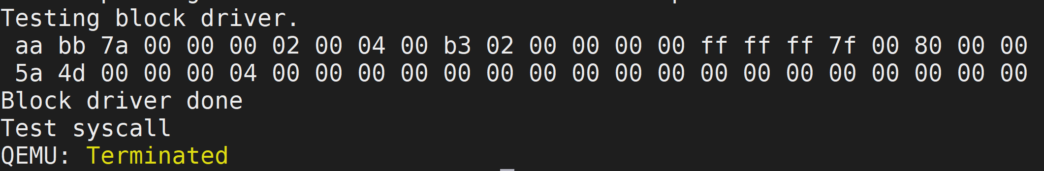
为了验证我们的结果,让我们看一下hdd.dsk文件的十六进制转储。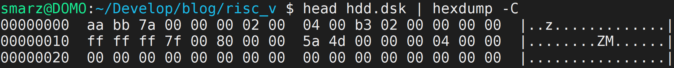
结论
探索期间发生了很多事情。当我第一次决定处理VirtIO规范时,我并没有意识到我将遇到的痛苦的挫折。不过,我想我现在已经牢牢掌握了事情的真相,但我愿意接受指正!